
D-60 A review will be made of measurement requirements and protocols for FRM OCR used for satellite validation based on existing protocols and peer-reviewed literature.
Validation of satellite OCR products requires measurements:
- following best practice, openly published protocols
- made with instruments with traceable SI calibration and characterized performance as regards wavelength accuracy, straylight, field of view, temperature stability, linearity, angular response for irradiance sensors,– see e.g. Table 2.2 of NASA Ocean Optics protocols For Satellite Ocean Color Sensor Validation, Revision 4, Volume II.
- accompanied by an uncertainty budget, which has been itself validated in Field Intercalibration Experiments
- that are openly and freely available and fully documented with metadata including deployment conditions (e.g. log book entry or auxiliary data for sea and sky state, photos of instrument, sea and sky, ), instrument calibration history, protocol and data processor versioning, etc.
These measurements can be achieved by a wide variety of methods including abovewater radiometry, underwater profiling, underwater measurements at fixed depths or combined above/underwater measurements from floating systems. Deployment platforms include fixed platforms, ships and tethered buoys. Even within each type of method there may be quite diverse protocols, e.g. abovewater radiometry can be performed with three-sensor systems measuring sea and sky radiance and downwelling irradiance or can be performed with sunphotometer systems, either automated or handheld, measuring sea and sky radiance and deducing downwelling irradiance from direct sun measurements combined with an atmospheric model.
It is expected that different measurement systems and protocols may be better adapted to different aquatic conditions. For example, abovewater radiometry involves large uncertainties at blue wavelengths in clear waters, where uncertainties in the “Fresnel” skyglint correction are significant compared to the water reflectance there. Conversely, underwater profiling systems have higher uncertainties in turbid waters and at red and a fortoriori near infrared wavelengths because of uncertainties in extrapolation of sub-surface data to the surface itself.
Although it is clearly preferable to harmonise whenever possible measurement protocols, and the discussions in Task 1 and experiments in Task 3 are expected to advance such harmonisation, diverse methods will be accepted provided that they meet the mandatory characteristics of a FRM as listed above and in section 3.3 of the SOW. Indeed measurement protocols found to give comparable data in the FICE to within the stated uncertainty budgets will justify the acceptance of diverse protocols.
Although not required by the SOW, In view of the popularity of abovewater radiometry using hyperspectral TRIOS/RAMSES within the S3VT, the Contractor will propose an open source prototype community processor for such data to advance standardisation of the measurement and as a basis for a possible future hyperspectral parallel to the AERONET-OC network (cf. RBINS’ HYPERNET-OC S3VT proposal).
The Tables of measurement and processing flags (MQC and PQC) already proposed for MERIS Validation data (see Tables 2-3 and 2-4 of MERIS Optical Measurement Protocols Part A: In-situ water reflectance measurements, CO-SCI- ARG-TN-008 Issue 2.0, August 2011 ESA/ARGANS will be used as a basis for a updated recommendation on metadata that should accompany data provided by S3VT members and on post-processing quality checks that can be applied. Refinements of this bookkeeping will include, in particular, traceability of the calibration history of each instrument used (referenced to serial number) and reference to the reports of any field intercomparison exercises.
As regards calibration history, although not mentioned in the SOW it is encouraged to perform relative calibration checks before/after each deployment and/or at regular intervals during long-term deployments and it is noted that this can be achieved at low cost by teams without dedicated laboratory facilities.
- As an example, Figure 4-3. shows a four year calibration history of an RBINS instrument used for MERIS Validation, where annual laboratory calibrations are supplemented with frequent calibration checks using a LED-based TRIOS FieldCAL light source, which has shown exceptional long-term stability. These checks can be performed rapidly (<30 minutes for 3 sensors) in the field with low-cost (<2000€) equipment without the need for a dedicated laboratory room, do not allow absolute calibration and enable relative tracking of any calibration drift between absolute calibration in dedicated laboratories. Such a procedure was, indeed, proposed already in the NASA Ocean Optics protocols, but the equipment available at that time, the SeaWiFS Quality Monitor (SQM), was much more expensive and time-consuming to
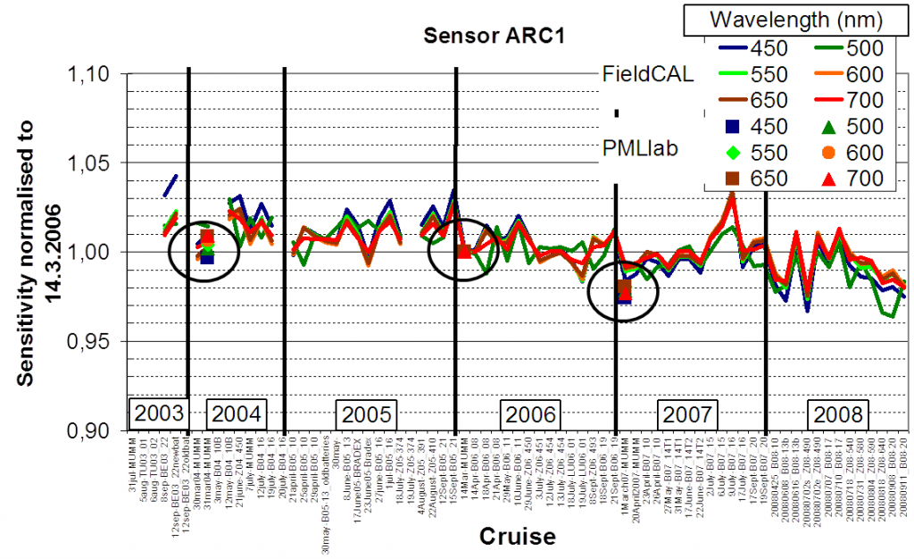
Figure 4-3. Calibration data for a TRIOS/RAMSES radiance sensor operated by RBINS/MUMM over the period 2003-8 with data from 3 laboratory absolute calibrations (symbols) and ~70 FieldCAL relative calibrations (solid lines) performed before/after each seaborne cruise. This data can be used to assess and calibration drift between laboratory calibrations and to identify smooth trends and/or sudden events (e.g. arising from instrument shocks). FieldCAL variability seen here is mainly related to the temperature dependency of the light source rather than radiometer variability.
-
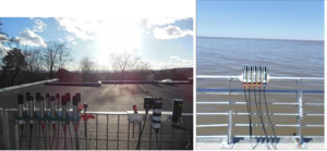
Figure 4-4. Installation of 15 radiometers of various manufacturer and type (radiance/irradiance) for calibration intercomparison using the sky as target (when cloud-free) (left) performed at NIVA during the HIGHROC project and (right) performed with 5 TRIOS radiances sensors (3*RBINS, 2*IAFE) in Buenos Aires during the TURBINET project.
As a second example, Figure 4-4. shows an installation for relative comparison of multiple radiometers set up to view a homogeneous sky Repetition of such intercomparison by a single measurement team with more than one radiometer of radiance/irradiance type can quickly identify calibration drift of any single instrument. Again this can be simply achieved without extra equipment (except for fixations and a suitable unshadowed roof area) by all teams.
- This intercomparison concept can be taken further in the relative comparison of radiance and irradiance radiometers by comparing a direct irradiance measurement with the corresponding value obtained by viewing a calibrated plaque with a radiance sensor, as in the “reflectance plaque” method described in Chapter 3 of Volume II of the NASA Ocean Optics
- A recommendation will be made to ESA for when measurements submitted/used by the S3VT and external parties can be accepted as FRM. The draft final report will be presented to the S3VT at a suitably timed meeting.
The Contractor will work closely with the Mission Performance Center and associated MERMAID-style database (if such exists) to facilitate practical uptake of recommendations and implementation for multi-partner validation analysis.
D-70 A review will also be made of commonly used Fiducial Reference Measurement (FRM) Ocean Colour Radiometers (OCR) for Satellite Validation
The protocols summarised in D-60 may be used with a variety of radiometers from different manufacturers, including both multispectral and hyperspectral designs. The integration of data from different instruments in a combined multi- partner validation analysis is a challenge, requiring good understanding of the performance of each instrument type and, as far as possible, each individual instrument. For example, Table 2.2 of the NASA Ocean Optics Protocols Revision 4, Volume II, specifies minimum performance characteristics for radiometers, including wavelength accuracy and stability, signal:noise ratio, straylight rejection, radiometric accuracy and stability, field of view, temperature stability and linearity. In addition the angular response of irradiance radiometers (“cosine response”) must be known and preferably corrected and the immersion factor of underwater radiometers must be known. In general the radiometers used in MERIS Validation activities were not characterised to his extent and, for example, there is only a little documented information on straylight and thermal stability for some sensor types.
For some characteristics, e.g. radiometric accuracy, wavelength accuracy and signal:noise ratio, it should be possible to occasionally characterise each individual instrument, e.g. during an annual calibration performed according to a standard procedure. These characteristics will be assessed in practice in Task 3.2.
For other characteristics, e.g. thermal stability, it may be necessary, for cost reasons, to characterise only a few specimens of each instrument type and suppose that individual instruments of a similar design will perform similarly.
Summary information will be provided for each instrument in the form of Table 4-2., where each characteristic of each instrument type will be summarised via a traceable reference such as a laboratory report or a peer-reviewed publication. In the case of missing characterisation for any instrument, the gap in knowledge will be flagged for the attention of ESA.
In addition to the summary table, each characteristic will be discussed in detail and recommendations for how such characterisation could be performed/sustained will be provided.
Characterisation of Polarisation sensitivity will be documented in addition to the characteristics already mentioned in the SOW, especially for abovewater radiometers, which view a highly polarised sea surface.
The draft final report will be presented to the S3VT at a suitably timed meeting.